
Cable-Stayed Bridges: How They Work, Types & Examples
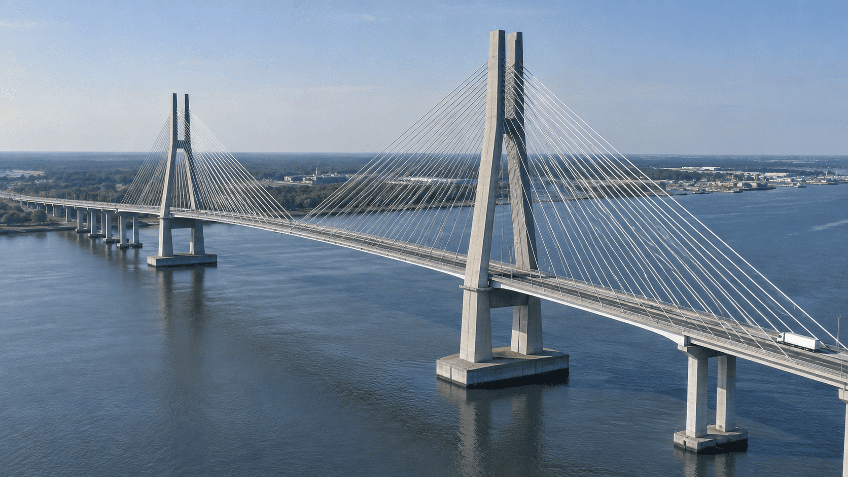
A cable-stayed bridge uses one or more towers, or pylons, and inclined stay cables that connect directly from the towers to the bridge deck. The cables work mainly in tension, while the towers carry much of the resulting force in compression, transferring loads from the deck through the structural system and ultimately into the foundations.
This design is especially effective for medium-to-long spans, where it can provide substantial stiffness while reducing the need for intermediate supports. Although cable-stayed bridges may resemble suspension bridges, the two systems are structurally different: a cable-stayed bridge does not use a separate main suspension cable with vertical hangers supporting the deck.
Understanding these bridges requires looking at how their forces are balanced, how their cable and tower configurations differ, how they are constructed, and where their advantages and limitations become important. The sections below examine those principles along with their main components, historical development, and notable modern examples.
How Do Cable-Stayed Bridges Work?
A cable-stayed bridge supports its deck with inclined cables that run directly between the deck and one or more towers, also called pylons. Instead of carrying the roadway on vertical suspenders hanging from a main cable, as a suspension bridge does, a cable-stayed bridge transfers loads through individual stay cables connected directly to the towers.
This arrangement creates an efficient structural system in which the cables, towers, deck, and foundations work together. The weight of the bridge itself, traffic, and other loads must ultimately reach the ground, and the stay cables provide a direct path for much of that force.
Tension, Compression, and the Load Path
The stay cables work primarily in tension, meaning they are pulled rather than compressed. When vehicles and the weight of the deck create downward forces, the inclined cables resist part of that load by pulling upward on the deck.
Those forces then travel along the cables toward the towers. Because the cables are inclined rather than vertical, each cable force can be understood as having two components: a vertical component that helps support the deck and a horizontal component that affects both the tower and the deck.
The towers carry much of the resulting force downward in compression. Compression occurs when a structural element is pushed or squeezed along its length. From the towers, the forces continue into the foundations and then into the supporting ground.
The deck also plays an active structural role. It is not simply a roadway suspended between towers. The horizontal components of the cable forces introduce significant compression into the deck, while the deck must also resist bending caused by traffic, its own weight, wind, and uneven loading.
In simplified terms, the load path is:
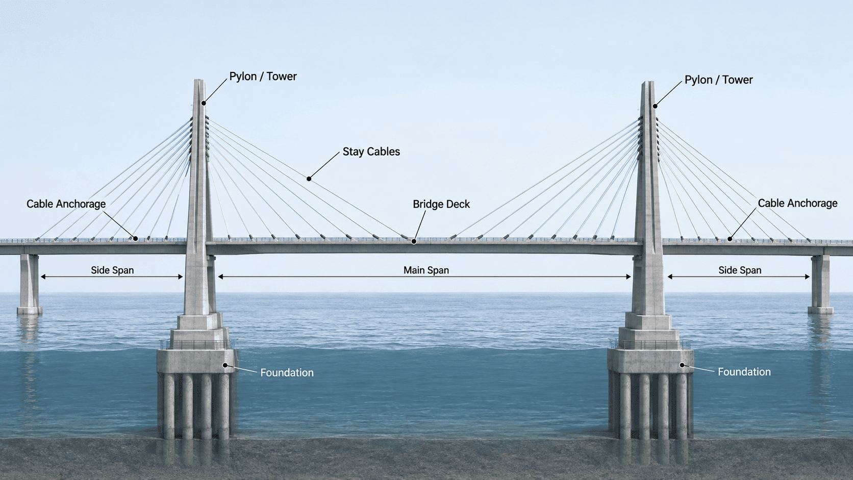
deck → stay cables → towers → foundations → ground
The actual structural behavior is more complex because forces are shared among many cables and parts of the deck, but this sequence explains the basic principle.
Why the Deck and Towers Stay in Balance
Cable-stayed bridges depend on a carefully balanced relationship between the forces acting on opposite sides of each tower.
When stay cables extend toward both the main span and the side spans, their horizontal forces can largely counteract one another. This reduces the tendency of the tower to be pulled strongly in only one direction. The tower can therefore transfer a large proportion of the remaining force vertically toward its foundation.
The deck helps maintain this balance by connecting the cable anchor points into a continuous structural system. Its stiffness limits excessive bending and distributes concentrated loads from individual cable connections across a larger portion of the bridge.
Balance does not mean that every cable carries the same force. Cable tension varies according to its position, angle, length, and the loads acting on the bridge. Traffic may also load one part of the deck more heavily than another, creating temporary changes in cable forces and deck deflection.
Engineers account for these differences so that the bridge remains stable under both permanent loads and changing conditions such as traffic and wind. The key principle is that the stay cables, deck, towers, and foundations do not work independently: each component contributes to a continuous system that redirects loads safely from the roadway to the ground.
Types of Cable-Stayed Bridges
Cable-stayed bridges can be classified in several ways. There is no single system that defines every “type.” Engineers may distinguish them by the pattern formed by the stay cables, the number and position of cable planes, or the number and arrangement of towers and spans.
These classifications describe different aspects of the same bridge. For example, a bridge may use a modified fan cable arrangement, two inclined cable planes, and two towers at the same time. Understanding the categories separately makes it easier to see how each design choice affects structural behavior and bridge geometry.
Cable Arrangements
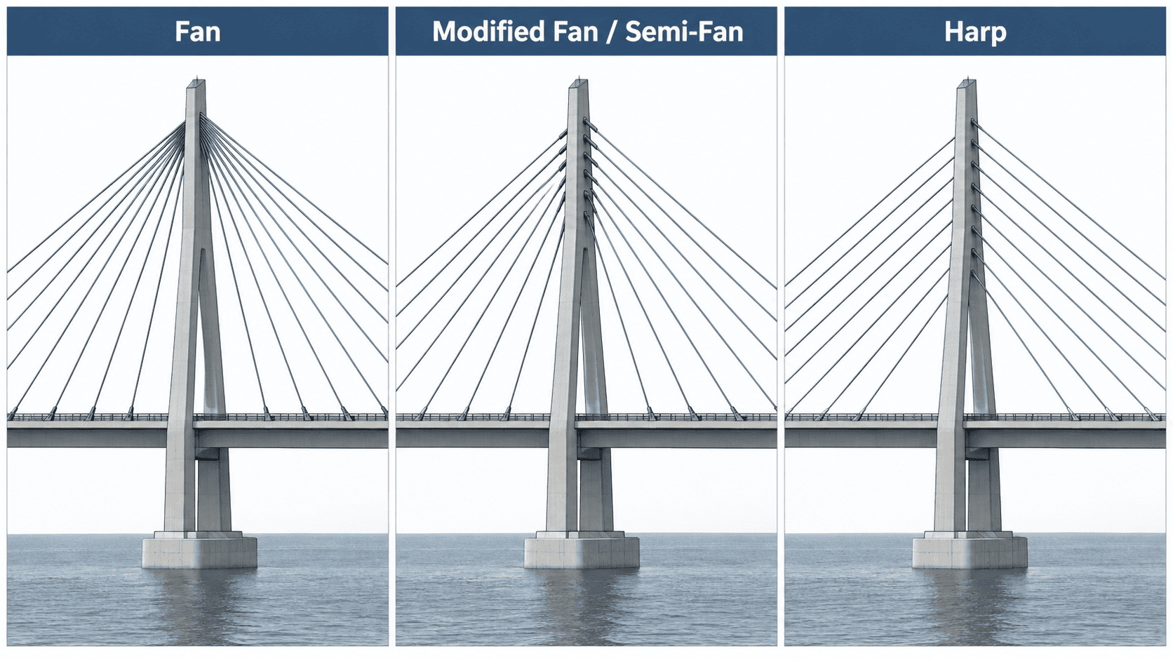
One of the most recognizable ways to classify cable-stayed bridges is by the pattern created by the stay cables when viewed from the side. The most common arrangements are fan, modified fan, and harp systems.
Fan
In a true fan arrangement, the stay cables spread outward from a common point, or from a very small zone, near the top of the tower. From there, the cables extend diagonally to different locations along the deck.
This geometry provides an efficient path for cable forces because the stays meet high on the tower and generally form favorable angles with the deck. It can reduce bending demands on the tower compared with arrangements in which cable anchorages are distributed over a larger vertical distance.
The main practical difficulty is congestion. Bringing many cables into nearly the same anchorage area creates limited space for connections and can complicate inspection and detailing at the top of the tower. For that reason, a geometrically perfect fan is less common in modern bridges than arrangements that spread the upper cable anchorages slightly apart.
Modified Fan or Semi-Fan
The modified fan, often called a semi-fan, keeps the basic appearance and structural advantages of a fan system but distributes the cable anchorages over the upper portion of the tower instead of concentrating them at one point.
This reduces anchorage congestion and gives designers more room to arrange cable connections. At the same time, the stay angles remain relatively efficient because most cables still connect high on the tower.
The semi-fan has therefore become one of the most widely used arrangements in modern cable-stayed bridges. It represents a practical compromise between the force efficiency of a fan and the easier detailing that comes from separating the tower anchorages.
Harp
In a harp arrangement, the stay cables are nearly parallel to one another. Their connections are distributed vertically along the tower and horizontally along the deck, producing a regular, repeated pattern.
The arrangement can create a clean and visually ordered appearance, which may influence its selection for bridges where architectural form is important. Structurally, however, distributing the cable connections down the height of the tower can produce greater bending in the tower than a fan or semi-fan configuration under some loading conditions.
Harp systems remain an important cable-stayed bridge configuration, but their selection involves balancing structural efficiency, tower behavior, and aesthetic objectives.
Mono and Other Less Common Arrangements
Some bridges use a mono-cable arrangement, in which stays appear to follow a more concentrated or simplified pattern rather than forming the conventional fan or harp layouts. Other designs combine features of established systems or use irregular cable spacing to respond to site constraints, asymmetric spans, or architectural requirements.
These variations should not automatically be treated as entirely separate structural bridge types. In many cases, they are adaptations of the same cable-stayed principle to a particular geometry or design requirement.
Cable Plane Arrangements
Cable-stayed bridges can also be classified by the number and position of the planes formed by their stay cables. Viewed across the width of the bridge, the stays may lie in a single central plane or in two planes placed on opposite sides of the deck.
Single Central Cable Plane
A single-plane system places the stays along the centerline of the bridge. This can give the structure a visually open appearance because cables are not positioned along both outer edges of the deck.
However, supporting the deck primarily along its centerline places greater importance on torsional stiffness—the deck's ability to resist twisting. Uneven traffic or wind loading can produce forces on one side of the deck that must be resisted without excessive rotation.
For that reason, the deck configuration must be capable of distributing loads effectively across its full width.
Two Vertical Cable Planes
With two vertical cable planes, stays are positioned on both sides of the deck and rise to corresponding anchorage zones on the towers. When viewed from the front, the two cable planes are approximately vertical.
Supporting the deck near both edges provides direct resistance to loads across its width and can reduce the deck's tendency to twist. This arrangement is common where structural efficiency and straightforward deck support are primary considerations.
Two Inclined Cable Planes
Two-plane systems can also incline inward from the deck edges toward the towers. From the front, the cables form angled planes rather than vertical ones.
Inclined cable planes can contribute to lateral stability while creating a distinctive bridge profile. Their geometry, however, introduces forces that must be considered across the width of the deck and in the tower configuration. The choice between vertical and inclined planes therefore affects both structural behavior and appearance.
Single-Tower, Two-Tower, and Multiple-Span Designs
A third classification considers the number of towers and the arrangement of spans.
A single-tower cable-stayed bridge uses one principal pylon, often with stays extending toward spans on both sides. This configuration may be appropriate for shorter crossings, asymmetric sites, or designs in which one dominant tower is desired.
A two-tower bridge is the familiar form used for many major crossings. Two pylons define the main span, while side spans extend toward the approaches. This configuration allows the stay system to support a substantial central span while maintaining structural balance on either side.
Cable-stayed systems can also extend across multiple spans and multiple towers. In these bridges, the interaction among adjacent towers becomes more complex because interior pylons may not have the same restraint provided by conventional side spans or anchor systems. Designers must therefore control tower movement and distribute forces carefully across the continuous structure.
The number of towers, cable planes, and cable pattern are related design decisions, but they describe different characteristics. Together, they allow cable-stayed bridges to be adapted to a wide range of crossing lengths, site conditions, structural requirements, and architectural forms.
Main Components of a Cable-Stayed Bridge
A cable-stayed bridge depends on several structural components working as one system. The most visible are the stay cables, towers or pylons, and deck, but the anchorages and foundations are equally important because they transfer and secure the forces generated throughout the structure.
The size, shape, and materials of these components vary from bridge to bridge. Engineers select them according to factors such as span length, deck width, expected traffic, wind conditions, site constraints, durability requirements, and construction feasibility.
Stay Cables
Stay cables provide direct support between the deck and the towers. Each stay is anchored at one end to the deck and at the other to a pylon. Together, the cables support the deck at multiple points along the span rather than allowing it to behave as one long unsupported beam.
Cable forces are carefully controlled because the amount of tension in each stay affects the position and internal forces of both the deck and towers. Individual cables may carry different loads depending on their length, angle, location, and the conditions acting on the bridge.
Modern cable-stayed bridges usually contain many separate stays. This creates a relatively dense support system in which loads can be distributed among numerous cable-to-deck connections.
Cable Materials and Protection
Stay cables are generally made from high-strength steel wires or strands assembled into larger cable systems. High-strength steel is used because cables must carry substantial tensile forces while remaining relatively slender.
The steel requires protection from corrosion because stay cables are continuously exposed to moisture, temperature changes, pollutants, and other environmental conditions. Modern systems may combine galvanization or other protective treatments with wax, grease, grout, or similar barriers and an outer protective sheath.
The visible outer covering is commonly made from durable polymer materials such as high-density polyethylene. In addition to limiting exposure to water and contaminants, cable systems can incorporate details intended to reduce rain- and wind-induced vibration.
Because stay cables are critical structural elements, modern designs also consider inspection, monitoring, and, where practical, eventual replacement without requiring the entire bridge to be rebuilt.
Towers or Pylons
The towers—often called pylons in cable-stayed bridge engineering—provide the elevated support points needed for the stay cables. Their height gives the cables sufficient inclination to support the deck effectively.
Pylons carry major compressive forces toward the foundations, but their behavior is not limited to simple vertical compression. Uneven traffic, wind, differences between adjoining spans, and other loading conditions can also create bending and lateral forces.
Tower dimensions therefore depend on more than appearance. Engineers must provide enough strength and stiffness to control movement while accommodating the forces introduced by the cable anchorages.
Common Pylon Shapes
Cable-stayed bridges use several recognizable pylon forms, including single-column, H-shaped, A-shaped, inverted-Y, and diamond-shaped towers.
Single-column pylons are often associated with bridges using a central cable plane. H-shaped towers use two vertical legs connected by crossbeams, providing a straightforward form for supporting cables on both sides of a wide deck.
A-shaped and inverted-Y pylons bring the tower legs toward one another above the roadway. This geometry can provide lateral stiffness while creating a distinctive visual profile. Diamond-shaped pylons extend this concept by joining or separating tower legs at different elevations.
No pylon shape is universally superior. The appropriate form depends on the cable-plane geometry, deck width, required clearance, structural forces, construction method, and architectural goals.
Bridge Deck
The deck carries traffic and forms the horizontal structural element spanning between the approaches and towers. In cable-stayed bridges, it must distribute local vehicle loads to the cable anchor points while also resisting bending, compression, twisting, and forces caused by wind.
A particularly important property is torsional stiffness, meaning resistance to twisting about the bridge's longitudinal axis. Adequate stiffness helps the deck remain stable when loads are unevenly distributed across its width.
Decks may be constructed primarily from steel, concrete, or a combination of both.
Steel Decks
Steel decks can achieve high strength with relatively low structural weight. Reducing deck weight is especially valuable for longer spans because the bridge must continuously support its own weight in addition to traffic and environmental loads.
Long-span steel designs often use streamlined box girders. A box girder is a hollow structural section whose closed shape provides strength and torsional stiffness while allowing the deck to remain comparatively light.
The tradeoff is that steel structures require careful fabrication and long-term corrosion protection.
Concrete Decks
Concrete decks are generally heavier than comparable steel systems but provide high stiffness, good compressive strength, and durable roadway structures when properly designed and maintained.
Their greater self-weight increases the permanent load carried by the cables and towers, so this must be considered when selecting concrete for longer spans. Prestressing is frequently used to control cracking and improve structural performance.
Concrete can nevertheless be highly effective for many cable-stayed bridges, particularly where local construction capabilities, material availability, economics, and span requirements favor it.
Composite Decks
Composite decks combine steel and concrete so the materials can perform complementary roles. A common configuration uses steel girders or structural framing together with a concrete roadway slab.
This approach can reduce weight compared with an all-concrete deck while retaining useful stiffness and roadway durability. Composite systems also allow designers to adapt the proportions of steel and concrete to the specific requirements of a crossing.
Anchorages and Foundations
Cable anchorages are the connection points where the stay forces enter the deck and towers. These connections must transfer concentrated tensile forces safely into much larger structural members while allowing cables to be installed, tensioned, inspected, and maintained.
At the base of the structure, foundations transfer tower and bridge loads into the ground. Depending on site geology and water depth, foundations may use large footings, drilled shafts, piles, caissons, or other deep-foundation systems.
Foundation design is especially important because the towers concentrate major forces at relatively limited locations. Engineers must evaluate soil or rock strength, settlement, scour around foundations in waterways, and lateral forces caused by wind, water, or seismic activity.
Although cables and towers define the appearance of cable-stayed bridges, their performance ultimately depends on every component—from the smallest cable anchorage to the foundations below ground—working within the same structural system.
Cable-Stayed Bridges vs Suspension Bridges
Cable-stayed and suspension bridges can look similar from a distance because both use towers and cables to support long spans. Their structural systems, however, are fundamentally different. The distinction lies mainly in how the cables connect to the deck and how forces are transferred through the bridge.
Structural Differences
In a cable-stayed bridge, each stay cable runs directly between the tower and the deck. The deck is therefore supported at many individual points by inclined cables.
A suspension bridge uses one or more large main cables that pass over the towers and continue toward massive anchorages at each end. The deck hangs below those main cables from vertical or nearly vertical suspenders.
This difference gives the two bridge types distinct structural behavior. Cable-stayed systems generally create a stiffer relationship between the deck and towers because the inclined stays provide direct support. Suspension systems allow the deck to hang from a flexible main-cable system, making control of deck movement and aerodynamic behavior especially important on very long spans.
| Feature | Cable-Stayed Bridge | Suspension Bridge |
|---|---|---|
| Primary cable system | Inclined stays connect directly from tower to deck | Main cables pass over towers; suspenders support the deck |
| Major ground anchorages | Usually not required for the main cable system | Typically essential to resist main-cable tension |
| Deck behavior | Generally stiffer | Generally more flexible |
| Typical span role | Medium to long spans | Long to extremely long spans |
| Common erection approach | Balanced cantilever construction | Main cables are established before much of the deck is suspended |
| Visual pattern | Multiple diagonal stays | Curved main cables with vertical suspenders |
Span, Stiffness, Anchorages, and Construction
Cable-stayed bridges are particularly competitive where a crossing is too long for many conventional girder systems but does not require the extreme span capability of a suspension bridge. Their relatively stiff deck-and-stay system can limit deflection under traffic and other changing loads.
Another major distinction involves anchorages. A conventional suspension bridge must transfer the enormous horizontal tension of its main cables into large anchor blocks or suitable rock formations at both ends. Most cable-stayed bridges do not need comparable external main-cable anchorages because opposing stay forces are largely balanced through the towers and deck system.
Construction also differs. Cable-stayed decks can often be extended outward from the towers in stages, with new stay cables supporting successive deck segments. Suspension bridges generally require the main cables to be erected first so that deck sections can later be hung from them.
When Is Each Bridge Type Used?
The choice depends on much more than span length. Engineers consider foundation conditions, navigation clearances, wind exposure, available construction methods, site geometry, cost, maintenance requirements, and architectural objectives.
Cable-stayed bridges are often favored for medium-to-long crossings where designers want a relatively stiff structure, fewer piers in the water, and construction that can proceed outward from the towers. Suspension bridges become increasingly attractive when the required main span reaches lengths at which the weight and structural demands of a cable-stayed system become less efficient.
There is no universal cutoff at which one system automatically becomes better than the other. Bridge type is selected by evaluating the complete site and structural requirements rather than span length alone.
How Cable-Stayed Bridges Are Built
The construction of a cable-stayed bridge is closely tied to its structural system. Unlike a conventional bridge that may require extensive falsework beneath the entire span, many cable-stayed bridges can be built outward from their towers while the stay cables progressively support newly added deck sections.
The exact sequence depends on span length, water depth, navigation requirements, site access, deck type, and available equipment. Two important approaches are balanced cantilever construction and erection with temporary supports.
Balanced Cantilever Construction
Balanced cantilever construction is one of the most characteristic methods used for cable-stayed bridges, especially where placing temporary supports below the main span would be difficult or undesirable.
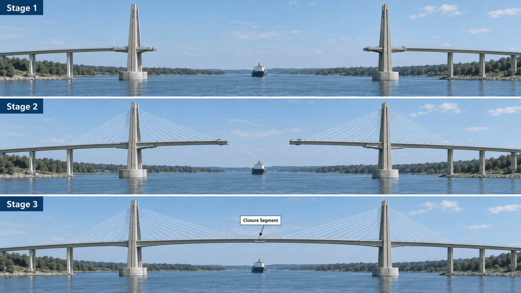
Construction typically begins with the foundations and towers. Once enough of a tower has been completed, short sections of the deck are erected near it. Additional deck segments are then added progressively outward.
As each new section is installed, a corresponding stay cable is connected between the deck and the tower and tensioned to provide support. The process continues segment by segment.
Whenever possible, construction advances on both sides of a tower in a relatively balanced sequence. Adding similar amounts of deck on opposite sides helps limit excessive unbalanced forces and bending in the tower during erection.
Deck segments may be lifted from barges, delivered from the completed portion of the bridge, or installed with specialized lifting equipment. Steel sections can be fabricated off-site and brought to the bridge for assembly, while concrete portions may be precast or cast in place depending on the design.
This method is particularly valuable over navigable waterways, deep valleys, or other locations where extensive temporary structures beneath the bridge would interfere with shipping, be difficult to construct, or add substantial cost.
Eventually, cantilevered portions extending from neighboring towers meet. A closure segment connects them, creating the continuous main-span deck.
Construction With Temporary Supports
Cable-stayed bridges can also be erected using temporary supports, sometimes called falsework or temporary piers. These structures carry portions of the deck during construction until the permanent stay system is capable of supporting them as intended.
This approach can be practical where the bridge crosses shallow water, land, or another location where temporary supports are relatively easy to install.
Temporary supports may simplify deck erection because sections can be placed onto stable intermediate points before the stay cables receive their final forces. They can also provide greater control over deck position during assembly.
However, the method becomes less attractive over deep water, busy navigation channels, environmentally sensitive areas, or very tall crossings because constructing and later removing temporary supports can be difficult and expensive.
Some projects use a combination of methods rather than relying exclusively on one technique. Temporary supports may be used in the side spans or near the approaches while balanced cantilever construction is used over the main obstacle.
Installing and Tensioning the Stay Cables
Stay cables are installed in a carefully planned sequence as construction progresses. One end is connected to an anchorage in the deck and the other to an anchorage in the tower. The cable is then tensioned using hydraulic equipment until it reaches the specified force.
Tensioning does more than simply tighten the cable. The force assigned to each stay helps establish the intended elevation and shape of the deck while controlling stresses in the bridge during construction.
As additional deck sections and cables are installed, forces in previously placed stays can change. Engineers therefore monitor cable tensions, tower movement, and deck alignment throughout erection. Some cables may be adjusted more than once before the bridge reaches its final configuration.
After the main structural system is complete, cable forces and deck geometry are checked and, when necessary, fine-tuned to match the design condition. Roadway finishes, barriers, lighting, expansion joints, drainage systems, and other components can then be completed before the bridge enters service.
Advantages and Limitations of Cable-Stayed Bridges
Cable-stayed bridges offer an effective combination of long-span capability, structural stiffness, and construction flexibility. Those advantages explain their widespread use for major highway and urban crossings. However, their performance depends on careful engineering, and the same cable system that makes them efficient also introduces specialized design, inspection, and maintenance challenges.
Advantages
One of the main advantages of cable-stayed bridges is structural efficiency. The stay cables provide support at many points along the deck, reducing the distance that deck sections must span without direct support. This allows the structure to carry substantial loads while using materials efficiently.
Cable-stayed bridges are also relatively stiff compared with suspension bridges of similar scale. Their direct connection between the deck and stay cables helps limit vertical movement under traffic and makes them well suited to crossings where excessive deflection would be undesirable.
Another benefit is the ability to cross wide rivers, navigation channels, and valleys with fewer intermediate piers. Reducing the number of supports in the obstacle below can preserve navigation clearance, decrease interference with waterways, and make construction possible where placing piers would be difficult.
Their structural arrangement is particularly compatible with balanced cantilever construction. Deck segments can be added progressively from the towers while newly installed stay cables provide support. This reduces the need for extensive temporary falsework beneath the main span.
Material efficiency is another important consideration. Because the deck receives frequent cable support, it can often be made relatively slender compared with a conventional girder bridge spanning the same distance. Designers can also select steel, concrete, or composite systems according to project requirements rather than relying on a single structural material.
Finally, cable-stayed bridges provide considerable architectural flexibility. Tower shape, cable geometry, deck profile, and span arrangement can be adapted to the site while still serving structural purposes. This flexibility has produced bridges with very different appearances without changing the fundamental cable-stayed principle.
Limitations and Engineering Challenges
Cable-stayed bridges are more complex to analyze and design than many shorter conventional bridges. Cable forces, tower movement, deck stiffness, wind effects, and construction sequence interact with one another, so changes in one part of the system can affect forces elsewhere.
The stay cables themselves require particular attention. Long, slender cables can experience vibration caused by wind, rain, traffic, or combinations of environmental effects. Excessive repeated movement can contribute to fatigue, the gradual accumulation of damage caused by repeated stress cycles. Engineers may use dampers, surface treatments, or other control measures to limit problematic vibration.
Corrosion is another long-term concern. Even though modern stay systems incorporate multiple protective barriers, moisture reaching high-strength steel can reduce durability. Inspection programs therefore monitor cable coverings, anchorages, corrosion protection, vibration behavior, and other signs of deterioration.
Access can make these inspections difficult. Cable anchorages may be located inside towers or within confined deck spaces, while the exposed length of a stay can extend tens or hundreds of feet above the roadway.
Very long cable-stayed spans also face increasing aerodynamic challenges. As spans grow, wind-induced movement of the deck, towers, and cables becomes increasingly important, requiring detailed aerodynamic analysis and sometimes wind-tunnel testing.
There is also a practical limit to the system's span efficiency. Longer spans require longer and heavier stays, taller towers, and greater control of deck and cable behavior. At extreme span lengths, suspension bridges may become more structurally efficient.
For this reason, the advantages of cable-stayed bridges are best understood as project-dependent. Their value comes from matching the structural system to the span, site conditions, construction constraints, environmental loads, and long-term maintenance requirements.
History and Development of Cable-Stayed Bridges
Although cable-stayed bridges are closely associated with modern engineering, the basic idea of supporting a bridge deck with inclined stays is centuries old. What changed dramatically during the twentieth century was the ability to analyze, build, and maintain the system efficiently enough for major transportation bridges.
Early Concepts and Hybrid Bridges
One of the earliest documented illustrations resembling a cable-stayed bridge appeared in Fausto Veranzio's Machinae Novae, published around 1615. His concept showed a bridge deck supported by inclined tension members extending from towers. It remained a conceptual precedent rather than the beginning of a continuous engineering tradition.
Practical experiments followed much later. During the eighteenth and nineteenth centuries, engineers built bridges that used inclined chains, rods, or cables to help support their decks. Some nineteenth-century structures combined these diagonal stays with suspension systems rather than using a purely cable-stayed arrangement.
The Albert Bridge in London, completed in 1873, is a notable example of this hybrid approach. Such bridges demonstrated that inclined stays could contribute effectively to supporting a span, but their structural behavior and materials differed significantly from those of today's cable-stayed bridges.
The Modern Cable-Stayed Bridge
The modern system emerged primarily in Europe during the decades surrounding World War II. German engineer Franz Dischinger developed influential ideas in the 1930s involving high-strength, prestressed inclined cables and more rigorous methods for analyzing their behavior.
A major milestone was Sweden's Strömsund Bridge, completed in 1955 and opened in 1956. It is widely described as the first major modern cable-stayed bridge, although bridge historians sometimes identify earlier structures, such as Eduardo Torroja's 1925 Tempul Aqueduct in Spain, as important precursors.
Strömsund demonstrated how a steel deck, towers, and prestressed stay cables could form an efficient modern bridge system. Its success helped stimulate rapid development of cable-stayed construction in Europe after the 1950s.
Longer Spans and Modern Materials
The following decades brought major improvements in high-strength steel cables, prestressed concrete, welding, structural analysis, corrosion protection, and construction equipment. Computer-based analysis later made it possible to model the complicated interaction among hundreds of structural elements and evaluate changing loads with far greater precision.
These advances allowed engineers to use more stays, support decks at shorter intervals, and design increasingly slender structures. Concrete and composite decks also expanded the range of economical design options beyond the predominantly steel decks of many early modern examples.
At the same time, improved aerodynamic analysis and wind-tunnel testing helped engineers address stability as main spans became longer. Cable-stayed bridges consequently progressed from comparatively modest postwar crossings to structures with main spans exceeding one kilometer.
Their historical development was therefore not the result of a single invention. It came from the gradual combination of an old structural idea with modern materials, analytical methods, construction techniques, and increasingly sophisticated control of cable and deck behavior.
Famous Cable-Stayed Bridges and Current Records
Cable-stayed bridges range from record-setting river crossings to urban structures designed around unusual site constraints. Their main-span lengths provide one useful measure of scale, but individual bridges are also notable for features such as multiple towers, extreme height, distinctive geometry, or pioneering construction.
Notable Cable-Stayed Bridges Around the World
The Changtai Yangtze River Bridge in Jiangsu Province, China, currently holds the world record for the longest cable-stayed main span at 1,208 meters (3,963 feet). Opened in 2025, the crossing combines highway, local road, and intercity rail functions in a large double-deck structure. Its span surpassed the record that had stood for more than a decade and demonstrates how modern cable-stayed design has moved beyond the 1,100-meter range.
Russia's Russky Bridge, connecting Vladivostok with Russky Island, has a 1,104-meter (3,622-foot) main span. When it opened in 2012, it established a world record for cable-stayed span length. Its exceptionally long stays and large-scale towers made it an important reference point in the development of very-long-span cable-stayed bridges.
The Millau Viaduct in southern France takes a different approach. Rather than relying on one exceptionally long central crossing, it uses seven piers and a series of spans, including six measuring 342 meters (1,122 feet) each. Completed in 2004 across the Tarn valley, the viaduct is especially notable for its multiple-span cable-stayed configuration and extraordinary height above the landscape.
France's Normandy Bridge, crossing the Seine estuary between the Le Havre and Honfleur areas, has an 856-meter (2,808-foot) main span. When it opened in 1995, it represented a major step forward in long-span cable-stayed engineering and helped demonstrate the feasibility of approaching the one-kilometer span range.
Major Cable-Stayed Bridges in the United States and North America
The Gordie Howe International Bridge crosses the Detroit River between Detroit, Michigan, and Windsor, Ontario. Its 853-meter (2,799-foot) main span is the longest cable-stayed span in North America. Opened to traffic on July 27, 2026, the bridge provides a direct highway connection between Interstate 75 in Michigan and Highway 401 in Ontario, making it both a major engineering project and an important international trade crossing.
In South Carolina, the Arthur Ravenel Jr. Bridge crosses the Cooper River between Charleston and Mount Pleasant. Its 1,546-foot (471-meter) main span made it one of North America's most significant cable-stayed bridges when it opened in 2005. The bridge is also notable for combining a major navigational clearance with an eight-lane roadway and pedestrian and bicycle access.
Florida's Sunshine Skyway Bridge carries Interstate 275 across Tampa Bay. Its cable-stayed section includes a 1,200-foot (366-meter) main span between two concrete pylons. Opened in 1987, it became an important U.S. example of a concrete cable-stayed bridge designed to provide substantial clearance over a major shipping channel.
Boston's Leonard P. Zakim Bunker Hill Memorial Bridge shows how the system can be adapted to difficult urban geometry. Its main span measures 745 feet (227 meters), considerably shorter than the other examples, but its asymmetric layout and hybrid steel-and-concrete structure make it technically distinctive. Rather than illustrating maximum span capability, the Zakim Bridge demonstrates the architectural and structural flexibility possible within cable-stayed design.
Related Entries: