
Bridge Parts: Main Components and Their Functions
Bridge parts are the structural and safety components that allow a bridge to carry traffic, cross an obstacle, and transfer loads safely into the ground. Although the exact arrangement varies among beam, truss, arch, suspension, cable-stayed, and movable bridges, most components belong to three main systems.
The foundation is the lowest system and transfers loads into soil or rock. The substructure includes piers, abutments, bearings, and other supports between the foundation and the spans. Above them, the superstructure carries vehicles, pedestrians, trains, or utilities across the crossing.
Understanding these three categories makes it easier to identify individual bridge components, follow the path of structural loads, and see how different parts work together as one complete system.
What Are the Main Parts of a Bridge?
Most bridge parts fall into three structural groups: the foundation, the substructure, and the superstructure. Together, these systems carry traffic loads, resist environmental forces, and transfer weight safely into the ground.
The foundation is the lowest part of the bridge. It may consist of shallow footings, piles, or pile caps that distribute loads into soil or rock. Above it, the substructure includes piers, abutments, bearings, and related supports. These components hold up the bridge spans and connect the visible structure to the foundation. The superstructure is the portion that crosses the obstacle. It includes the deck, beams, girders, trusses, railings, and other elements that directly support vehicles, pedestrians, or trains.
A labeled bridge diagram helps show how these three structural groups fit together from the ground upward.
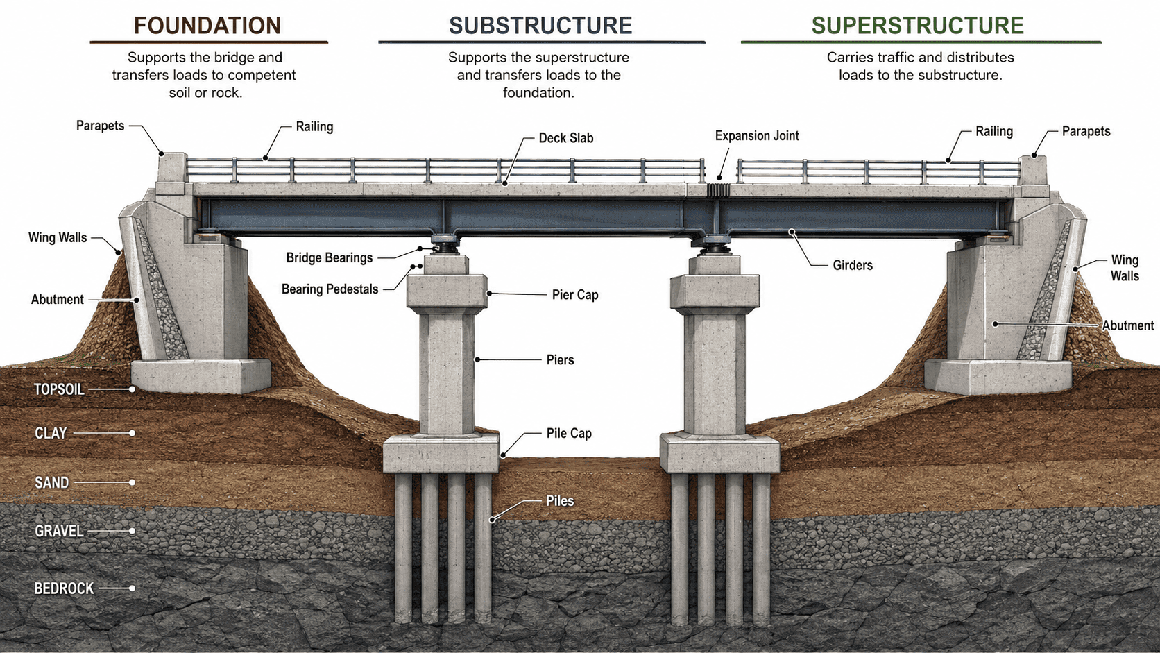
| Main category | General function |
|---|---|
| Foundation | Transfers bridge loads into soil or rock |
| Substructure | Supports the spans and connects them to the foundation |
| Superstructure | Carries traffic and spans the obstacle |
Although the exact components vary by bridge type, this three-part framework provides the clearest way to understand bridge anatomy.
Bridge Foundation Components
Bridge foundations form the lowest structural system of a bridge and transfer loads from the substructure into the supporting soil or rock. The type used depends on ground conditions, water depth, expected loads, and the risk of settlement or scour. In general, bridge foundations are either shallow, when competent material lies near the surface, or deep, when loads must be carried to stronger layers below.
Shallow Foundations (Open Foundations)
A shallow foundation, sometimes called an open foundation, supports an abutment or pier close to ground level. It usually consists of a reinforced concrete footing placed on firm soil or exposed rock. The footing spreads the loads received from the substructure across a wider area, helping keep soil pressure within acceptable limits and reducing uneven settlement.
Shallow foundations are most practical where stable bearing material is readily accessible and erosion is not expected to undermine the support. They are less suitable where weak soils extend to significant depths or where river scour could remove material around the footing.
Piles
Piles are long structural members driven, drilled, or cast into the ground to create a deep foundation. Common bridge piles are made of reinforced or prestressed concrete, structural steel, or treated timber. They are used when near-surface soils cannot safely support the bridge.
A pile may transfer loads through end bearing, where its tip rests on dense soil or rock; through skin friction, where resistance develops along its sides; or through a combination of both. Groups of piles can also resist lateral forces caused by wind, water, traffic, or earthquakes.
Pile Caps
A pile cap is a thick reinforced concrete element built over a group of piles. It ties the individual piles together and distributes loads from a pier or abutment among them. By acting as a single structural unit, the pile cap helps prevent one pile from carrying a disproportionate share of the load and provides a stable base for the substructure above.
Bridge Substructure Components
The bridge substructure lies between the foundation and the superstructure. Its components support the spans, transfer loads downward, and help the bridge accommodate movement caused by traffic, temperature changes, wind, water, and earthquakes. Because these elements often stand near roadways or in waterways, they may also need to resist impacts, flowing water, debris, and soil pressure.
Piers and Pier Caps
Piers are vertical supports located between the bridge’s end supports. They carry intermediate spans and transfer loads from the superstructure to the foundation below. Depending on the bridge, a pier may be a solid wall, a single column, or a group of columns. A framed group of columns joined by a cap is sometimes called a bent. In addition to vertical weight, piers may resist lateral forces from wind, currents, braking vehicles, and seismic motion.
A pier cap is the horizontal member at the top of a pier. It spreads loads across the supporting columns and provides seats for girders or bridge bearings. On multi-girder bridges, the cap helps distribute forces from several parallel members into the pier while maintaining the required spacing and alignment of the supports.
Bearing Pedestals and Bridge Bearings
A bearing pedestal is the raised concrete or steel support on which a bridge bearing rests. It creates a level bearing seat, provides clearance, and helps transmit concentrated forces into a pier cap or abutment. Pedestals can also make bearings easier to inspect, maintain, or replace without altering the larger support.
The bearing itself sits between the substructure and superstructure. It transfers vertical loads while allowing controlled rotation or movement as the bridge expands, contracts, or deflects. Elastomeric bearings use layers of rubber, often reinforced with steel, to accommodate small movements and rotations. Pot bearings are designed for heavier loads and greater rotation. Sliding bearings allow one surface to move relative to another, helping longer spans respond to thermal expansion.
Seismic Restrainers and Vertical Bearings
Seismic restrainers, sometimes called seismic arrestors, limit excessive movement between bridge components during an earthquake. They may connect adjacent spans or tie the superstructure to piers and abutments, reducing the risk that a span will move far enough to leave its support.
Vertical or hold-down bearings are used where uplift or reversing forces may occur. Unlike conventional bearings that primarily carry downward compression, these devices help keep the superstructure attached to its supports when wind, seismic action, or structural geometry produces upward forces.
Abutments and Wing Walls
Abutments support the ends of a bridge and connect the structure to the roadway or railway approaches. They receive loads from the end spans, transfer those loads to the foundation, and retain the soil behind the bridge. Many abutments also provide bearing seats and help form a stable transition between the bridge deck and the approach pavement.
Wing walls extend from the abutments along the sides of the approach embankment. Their main purpose is to hold back fill, reduce soil erosion, and guide the transition between the bridge and the adjoining roadway. Their shape and orientation depend on the site, available space, and direction of the retained soil.
Pier Crash Barriers
Pier crash barriers protect vulnerable bridge supports from vehicle impacts. They may be placed around piers near highways, parking areas, rail corridors, or other locations where an errant vehicle could strike a structural column. These barriers are separate from the parapets and railings installed along the edges of the bridge deck. Their purpose is to absorb or redirect impact before it reaches the pier.
Bridge Superstructure Components
The superstructure is the portion of a bridge that spans the roadway, waterway, valley, or other obstacle. It carries traffic and transfers loads to bearings, piers, and abutments. Although its exact form depends on the bridge type, the superstructure usually includes the deck, primary load-carrying members, stabilizing elements, safety barriers, and movement joints.
Girders, Beams, and Trusses
Girders are the main horizontal members that support the deck and carry loads across the span. The terms beam and girder are sometimes used interchangeably, although a girder generally refers to a larger primary member that supports smaller beams or the deck directly.
Plate girders are fabricated from steel plates joined to form a deep web and flanges. Box girders have a hollow rectangular or trapezoidal shape that provides high torsional stiffness, making them useful on curved bridges. Concrete girders may be reinforced or prestressed, while steel girders are valued for strength and longer-span capability. Trusses perform a similar spanning function through interconnected members arranged in triangles, which distribute tension and compression efficiently.
Bridge Parapets and Railings
Parapets and railings protect bridge users and help keep vehicles, pedestrians, or cyclists from leaving the deck. Vehicle barriers are designed to redirect or contain an errant vehicle. Pedestrian railings are proportioned to prevent falls while maintaining visibility. A parapet is a solid or partially solid barrier built along the edge of the deck.
These features are essential safety components, but they are generally not part of the bridge’s primary load-carrying system. Their design must still account for impact forces, weather exposure, and connections to the deck.
Deck Slab
The deck slab forms the traveled surface of the bridge and directly receives loads from vehicles, pedestrians, bicycles, or trains. It distributes those loads to the beams, girders, or trusses below.
Concrete decks are common because of their stiffness and durability. Steel decks reduce weight and may be used where a lighter superstructure is advantageous. Composite decks act together with steel girders through mechanical connectors, allowing both materials to share loads. Timber decks remain in use on some short-span, rural, temporary, or historic bridges.
Diaphragms and Bracing
Diaphragms are transverse members placed between adjacent girders. They help maintain spacing, distribute lateral forces, and stabilize girders during construction and service. Depending on the design, they may be made of steel, reinforced concrete, or other structural materials.
Cross-bracing and lateral bracing connect major members diagonally or horizontally. These systems resist sideways movement, improve overall stiffness, and help control twisting caused by wind, curved geometry, or uneven loading. Diaphragms usually connect neighboring girders at specific locations, while bracing forms a broader system of structural ties.
Rail Plinths and Specialized Supports
Rail plinths are raised concrete supports used mainly on railroad and transit bridges. They provide a stable base for rails and fastening systems, maintain track alignment, and transfer train loads into the deck.
Some bridges also carry utility supports for pipes, conduits, or cables. Hanging systems may be installed beneath or beside the deck to support these services without interfering with the primary structural members.
Expansion Joints
Expansion joints are installed at selected breaks in the deck to accommodate movement caused by temperature changes, concrete shrinkage, structural deflection, and repeated traffic loading. Without sufficient movement space, stresses can build up and damage the deck, barriers, or supporting elements.
Bearings and expansion joints work together but serve different roles. Bearings allow controlled movement and rotation between the superstructure and substructure, while expansion joints provide a physical gap or flexible connection at deck level so adjacent sections can move without pressing against one another.
How Bridge Parts Change by Bridge Type
Most bridges use the same basic foundation, substructure, and deck components, but the primary system carrying loads across the span changes with the bridge type.
Beam and Girder Bridges
Beam and girder bridges rely on horizontal members supported by abutments and, on longer crossings, intermediate piers. The deck transfers traffic loads into the beams or girders, which resist bending and carry those forces toward the supports. Short spans may use simple concrete beams, while longer or curved spans often require steel plate girders or box girders.
Truss and Arch Bridges
A truss bridge uses interconnected members arranged in triangular patterns. These members carry loads mainly through tension and compression, allowing the structure to span greater distances while using material efficiently.
An arch bridge follows a different load path. Its curved structural members carry most forces through compression and direct them outward and downward into the abutments. Because of this horizontal thrust, arch bridges require strong end supports and suitable foundation conditions.
Suspension and Cable-Stayed Bridges
Suspension bridges use towers, main cables, vertical suspenders, and large anchorages. The deck hangs from the main cables, which pass over the towers and transfer tension forces into anchorages at each end.
Cable-stayed bridges also use towers, but their inclined stays connect the deck directly to the towers rather than hanging from a separate main cable. Cantilever bridges extend outward from supports using projecting structural arms, while movable bridges add machinery, counterweights, pivots, or lifting systems that allow part of the span to open for marine traffic.
How Bridge Parts Work Together to Carry Loads
Bridge components function as a connected load path rather than as isolated parts. When a vehicle crosses a bridge, its weight creates a live load, meaning a temporary load that changes as traffic moves. The deck receives this force and spreads it across the supporting beams, girders, or trusses.
These primary structural members carry the load across the span and direct it toward the bridge supports. Bearings then transfer the forces into the piers and abutments while allowing the controlled movement and rotation required by temperature changes and structural deflection.
Piers carry loads from intermediate spans, while abutments support the ends of the bridge. Both direct these forces into footings, pile caps, or other foundation components. The foundation then distributes the loads into stable soil or rock through shallow bearing surfaces, piles, or a combination of both.
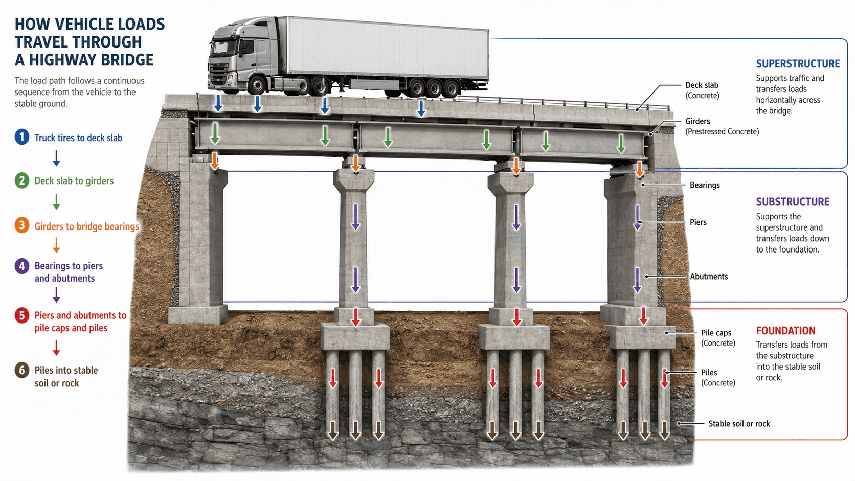
For example, the weight of a truck moves from its tires into the deck, through the girders and bearings, down the piers, and finally into the ground. A safe bridge depends on every component maintaining this continuous load path.
Related Entries: