Truss Bridge: Design, Types, History, and Uses
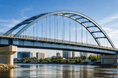
A truss bridge is one of the most important bridge designs in engineering because it combines strength, stability, and efficient use of materials. By using a framework of connected members, usually arranged in triangular patterns, a truss bridge can distribute loads across a span instead of relying on a single solid beam. This makes it useful for roads, railways, pedestrian crossings, temporary structures, and historic bridge construction.
In the United States, truss bridges played a major role in the growth of transportation networks, especially during the expansion of covered bridges, railroads, iron bridges, and steel highway structures. Understanding how truss bridges work requires looking at their design, deck arrangements, span systems, major truss types, advantages, limitations, and common uses.
What Is a Truss Bridge?
A truss bridge is a bridge whose main load-bearing structure is made of connected structural members arranged in a truss, usually a pattern of triangles. Instead of relying on one solid beam to carry weight, a truss bridge distributes forces through a network of straight members. This makes the structure strong, stable, and efficient for carrying vehicles, trains, pedestrians, or other loads across a span.
Basic Definition of a Truss Bridge
In engineering, a truss is a framework made of individual members connected at joints. In a truss bridge, these members work together to support the deck, which is the part of the bridge where traffic or pedestrians pass. The members may be made of wood, iron, steel, or modern structural materials, depending on the age, purpose, and design of the bridge.
A key feature of a truss bridge is that its members are mainly designed to carry either tension or compression. Tension is a pulling force, while compression is a pushing force. By separating these forces across different parts of the structure, a truss bridge can support heavy loads while using less material than many solid bridge forms.
Why Truss Bridges Use Triangles
Triangles are central to truss bridge design because they are naturally stable shapes. A square or rectangle can distort under pressure unless it is reinforced, but a triangle keeps its shape when force is applied to its joints.
This triangular arrangement allows loads to move efficiently through the structure and into the bridge supports. As a result, truss bridges can achieve a strong balance between strength, span length, and material efficiency.
Truss Bridge Design
Truss bridge design is based on the idea that a bridge can carry heavy loads more efficiently when forces are divided among many connected members instead of concentrated in one large beam. The overall shape, member arrangement, deck position, and connection points all affect how the bridge performs. A well-designed truss bridge balances strength, stiffness, weight, span length, and construction cost.
Main Structural Components
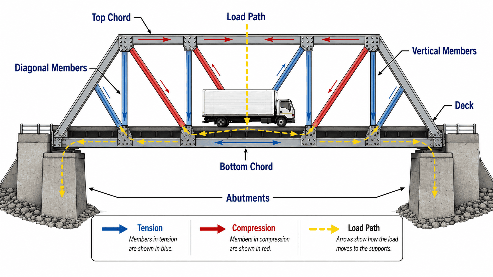
The main parts of a truss bridge include chords, web members, joints, and the deck. The top chord is the upper horizontal or curved member of the truss, while the bottom chord runs along the lower part of the structure. These chords help define the overall shape of the bridge and carry major internal forces.
Between the chords are vertical and diagonal members, often called web members. These pieces create the triangular pattern that gives the truss its strength. The joints are the connection points where members meet, and they must transfer forces safely from one member to another. The deck is the surface that supports traffic, pedestrians, or rail lines.
Tension and Compression
The efficiency of a truss bridge comes from the way its members handle tension and compression. Tension is a pulling force that stretches a member, while compression is a pushing force that squeezes it. In a typical truss, some members are designed mainly to resist tension, while others are designed mainly to resist compression.
This separation of forces allows engineers to use material where it is most effective. For example, steel performs very well in tension and compression, making it common in many modern and historic truss bridges. Wood was also widely used in earlier American truss bridges, especially in covered bridges and shorter rural spans.
How Loads Move Through a Truss
When a vehicle or train crosses a truss bridge, the load first acts on the deck. From there, the force moves into floor beams, stringers, and the truss members. The triangular framework spreads the load through the structure instead of allowing it to bend one single element excessively.
The load then travels through the connected members toward the supports, also called abutments or piers. Abutments are supports at the ends of a bridge, while piers are intermediate supports used in longer bridges. This path of force is one reason truss bridges can span significant distances while remaining relatively lightweight.
Model Truss Bridges
Model truss bridges are often used in classrooms, engineering programs, and bridge-building competitions because they show the principles of structural design in a simple way. Small models made from wood sticks, cardboard, or lightweight materials can demonstrate how triangles improve stability and how different truss patterns change load capacity.
These models also help students understand failure points. A member may buckle under compression, snap under tension, or fail at a weak joint. By testing a model truss bridge, learners can see why careful geometry, strong connections, and balanced load paths are essential in real bridge design.
History of Truss Bridges in the United States
Truss bridges became especially important in the United States because they matched the country’s need for practical, economical crossings over rivers, valleys, canals, and expanding transportation routes. As American towns, farms, railroads, and industries grew, builders needed bridges that could span longer distances without requiring massive amounts of material. The truss bridge offered a strong solution by combining simple geometry with efficient use of wood, iron, and later steel.
Early Timber Truss Bridges
Many early American truss bridges were built with timber because wood was widely available and relatively easy to work with. In rural areas, timber trusses allowed builders to create stronger and longer bridges than simple beam bridges. These early structures often depended on craftsmanship, local materials, and practical knowledge rather than modern engineering analysis.
Timber truss designs were especially useful where stone arches were too expensive or difficult to build. By arranging wooden members into triangular frameworks, builders could create bridges that were lighter than masonry structures but still capable of carrying wagons, livestock, and local traffic.
Covered Bridges
Covered bridges became one of the most recognizable forms of timber truss construction in the United States. The roof and side coverings were not mainly decorative; they helped protect the wooden truss members from rain, snow, and direct sunlight. This protection extended the service life of the bridge by reducing decay and weather damage.
Many covered bridges used truss patterns such as the Town lattice, Burr arch truss, or Howe truss. These designs became common in the 19th century, especially in rural communities where durable crossings were essential for trade, farming, and daily travel.
Iron and Steel Truss Bridges
As industrial production expanded, iron and steel began to replace timber in many truss bridges. Metal members allowed bridges to carry heavier loads, span longer distances, and better serve growing transportation networks. Iron was used in many early metal truss bridges, while steel later became the dominant material because of its strength, consistency, and suitability for tension and compression.
This transition also changed bridge construction methods. Instead of relying only on local carpentry, bridge building increasingly involved standardized components, engineering calculations, and specialized manufacturing.
Railroad Expansion and Standardization
Railroad growth played a major role in the development of truss bridges in the United States. Trains were much heavier than wagons or pedestrians, so railroad bridges required stronger and more predictable structural systems. Truss bridges were well suited to this need because their members could be designed to carry specific forces.
Over time, many truss bridge forms became standardized for railroad and highway use. Standardization made bridges easier to design, fabricate, inspect, and maintain. It also helped spread recognizable truss types across the country, including Pratt, Warren, Howe, Baltimore, and Pennsylvania trusses.
Truss Bridge Deck Types
Truss bridge deck types are classified by the position of the roadway, railway, or walkway in relation to the truss structure. In other words, the deck type describes where traffic moves: above the truss, through the truss, or between lower side trusses. This arrangement affects clearance, appearance, structural behavior, construction needs, and how the bridge is used.
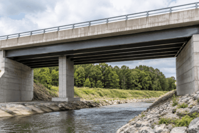
Deck Truss Bridge
A deck truss bridge has its deck placed on top of the truss structure. The main truss members are below the roadway or railway, so users typically travel over the structural framework rather than through it. This design is often useful when a bridge must cross a deep valley, canyon, river, or roadway where there is enough space below the deck for the truss system.
One advantage of a deck truss bridge is that the truss can be placed underneath the traffic surface without limiting side clearance for vehicles. However, this design usually requires enough vertical space below the deck, making it less suitable in locations where clearance beneath the bridge is limited.
Through Truss Bridge
A through truss bridge carries traffic through the truss structure. In this design, the deck is located between two large side trusses, and overhead lateral bracing may connect the upper portions of the trusses. Lateral bracing refers to members that help resist side-to-side movement and improve stability.
Through truss bridges are common in historic highway and railroad construction because they can support longer spans while keeping the main structural depth above and beside the deck. However, the overhead and side framing can limit the height and width of vehicles that pass through the bridge.
Pony Truss Bridge
A pony truss bridge is similar to a through truss bridge, but it does not have overhead bracing connecting the tops of the side trusses. The deck still runs between the trusses, but the trusses are shorter and open at the top. This makes pony truss bridges common for shorter spans where full overhead bracing is not necessary.
Because they lack top bracing, pony truss bridges must be designed carefully to resist lateral movement. They are often used for roadways, small crossings, and rural bridges where moderate span length and practical construction are more important than very high load capacity.
Half-Through Truss Bridge
A half-through truss bridge is a variation in which the deck is positioned partway between the top and bottom of the truss. The traffic passes between the side trusses, but the structural arrangement does not fully match a standard through truss or pony truss. This type can be useful when designers need a compromise between clearance, structural depth, and site conditions.
The choice between deck, through, pony, and half-through arrangements depends on span length, required clearance, expected loads, and the physical limits of the bridge location.
Single-Span and Multiple-Span Truss Bridges
Truss bridges can also be classified by the number of spans they use. A span is the distance between two supports, such as abutments or piers. This classification matters because the number and arrangement of spans affect bridge length, structural behavior, construction complexity, and the type of truss system that may be appropriate for the site.
Single-Span Truss Bridges
A single-span truss bridge crosses the full distance between two end supports without intermediate piers. This arrangement is common for shorter crossings, such as small rivers, rural roads, canals, or pedestrian routes. Because the entire load must be transferred to the two end supports, the truss must be strong enough to carry traffic across the full opening.
Single-span truss bridges are often simpler to design, inspect, and maintain than more complex bridge systems. They can also be useful where placing a pier in the water, roadway, or valley below would be expensive, difficult, or environmentally sensitive.
Multiple-Span Truss Bridges
A multiple-span truss bridge uses more than one span to cross a longer distance. Intermediate supports divide the total crossing into shorter sections, allowing the bridge to cover wide rivers, floodplains, rail corridors, or large valleys. Each span may function as a separate truss, or the structure may be designed so that forces interact between spans.
This arrangement can reduce the length and weight of each individual truss, but it also increases the number of supports, foundations, bearings, and inspection points.
Continuous Truss Bridges
A continuous truss bridge extends over more than two supports as one connected structural system. Unlike a series of simple spans, a continuous truss distributes loads across multiple supports. This can reduce bending in certain parts of the structure and improve efficiency for longer crossings.
However, continuous truss bridges require careful engineering because forces shift across the structure depending on where loads are applied.
Cantilever Truss Bridges
A cantilever truss bridge uses projecting arms that extend outward from piers or anchor points. These arms may support a central suspended span or meet in the middle. Cantilever trusses are useful for long crossings where temporary support from below is difficult, such as over deep water or busy navigation channels.
Main Types of Truss Bridges
Truss bridges can be classified by the pattern of their members and by the way those members handle tension, compression, and load transfer. Each type developed to solve a specific engineering problem, such as increasing span length, reducing material use, improving stiffness, or simplifying construction. The most common truss bridge types are usually identified by the arrangement of their diagonal and vertical members.
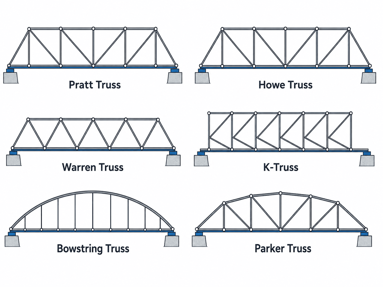
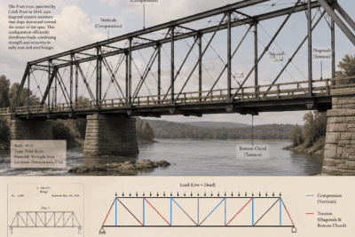
Pratt Truss Bridge
The Pratt truss bridge is one of the most recognizable truss designs in the United States. It uses diagonal members that typically slope downward toward the center of the span. In this arrangement, the diagonal members usually carry tension, while the vertical members carry compression.
This made the Pratt truss especially effective for metal bridge construction, because iron and steel perform well in tension. The design became widely used for railroad and highway bridges during the 19th and early 20th centuries. Its clear force pattern, practical fabrication, and adaptability helped make it one of the most influential truss bridge forms.
Howe Truss Bridge
The Howe truss bridge uses diagonal members that slope in the opposite direction from those in a Pratt truss. In a traditional Howe truss, the diagonal members are mainly in compression, while the vertical members are mainly in tension.
This design was especially useful in timber bridge construction because wood performs well under compression. Many covered bridges used Howe truss systems or related timber truss patterns. As metal rods became easier to produce, some Howe trusses combined wooden diagonal members with iron vertical rods, creating a practical hybrid system for 19th-century bridge building.
Warren Truss Bridge
The Warren truss bridge uses a series of equilateral or near-equilateral triangles. Unlike Pratt and Howe trusses, it often does not require many vertical members, although some versions include them for added support. The repeated triangular pattern allows loads to be distributed across the structure in a relatively even way.
Warren trusses became popular because they use material efficiently and have a simple, clean geometry. They are often seen in highway, railway, and pedestrian bridge applications. Their balanced pattern can work well for medium spans, but the exact performance depends on the span length, load requirements, and whether vertical members are included.
K-Truss Bridge
A K-truss bridge divides larger truss panels into smaller triangular sections shaped somewhat like the letter K. This design reduces the unsupported length of compression members, which can help limit buckling. Buckling occurs when a compressed member bends or fails sideways under load.
The K-truss was often used where engineers wanted greater stiffness and better distribution of forces across a deeper truss. However, its more complex arrangement can make design, fabrication, and inspection more demanding than simpler truss types. For that reason, it is usually discussed as a specialized design rather than the most common choice.
Baltimore Truss Bridge
The Baltimore truss is a variation of the Pratt truss. It adds extra sub-divided members in the lower part of the truss panels, helping the bridge handle heavier loads and longer spans. These added members improve support for the deck and reduce stress in certain parts of the structure.
Baltimore trusses were especially useful for railroad bridges because trains create heavy, concentrated loads. The design gave engineers a way to strengthen the basic Pratt system without completely changing its structural logic. Its use reflects the demand for stronger and more reliable bridges during the expansion of rail transportation.
Bowstring Truss Bridge
A bowstring truss bridge combines an arched top chord with a straighter bottom chord, creating a shape similar to a drawn bow. The curved upper chord helps carry compression, while the lower chord acts like a tie that resists outward thrust.
This type became common in some early metal bridges because it offered an efficient way to span moderate distances with a visually distinctive form. Bowstring trusses are often associated with historic bridge design and are valued today for both their engineering significance and architectural character.
Parker or Camelback Truss Bridge
The Parker truss is another variation of the Pratt truss, but it uses a polygonal top chord instead of a straight one. This means the upper chord changes slope along the span, allowing the truss to be deeper near the center, where bending forces are usually greater.
A camelback truss is a specific form of Parker truss with a top chord made of a limited number of straight slopes, often creating a more symmetrical profile. These designs use material efficiently because the truss depth better follows the structural demand along the span. They were commonly used for longer highway and railroad crossings.
Bailey Truss Bridge
The Bailey truss bridge is a portable, prefabricated truss bridge developed during World War II [VERIFICAR]. It is made from modular panels that can be assembled quickly without heavy specialized equipment. This made it especially valuable for military use, emergency crossings, and temporary infrastructure.
The strength of the Bailey system comes from its modular flexibility. Panels can be added side by side or stacked to increase capacity. Although originally associated with military engineering, Bailey-type bridges have also been used in disaster response and temporary civilian crossings.
Burr Arch Truss Bridge
The Burr arch truss combines a timber arch with a truss framework. The arch helps carry the main load, while the truss adds stiffness and stability. This combination was widely used in American covered bridges.
The Burr arch truss was practical because it joined two strong structural ideas: the load-carrying ability of an arch and the bracing efficiency of a truss. Many surviving covered bridges use this system, making it one of the most historically important timber truss forms in the United States.
Cantilever Truss Bridge
A cantilever truss bridge uses arms that project outward from piers or anchor points. These cantilevered arms can support a central suspended span or meet near the middle. The design is useful where building temporary supports from below would be difficult, such as over deep water, wide rivers, or navigation channels.
Cantilever truss bridges can achieve long spans while allowing construction to proceed outward from stable supports. However, they require careful engineering because the projecting arms must resist large bending and balancing forces during construction and service.
Kingpost and Queenpost Truss Bridges
The kingpost truss is one of the simplest truss forms. It uses a central vertical post with diagonal members extending to the ends of the span. Because of its simplicity, it is usually suitable for short spans, small bridges, roofs, or light-duty structures.
The queenpost truss is slightly more complex. It uses two vertical posts instead of one, allowing a longer central section and a somewhat greater span. Both kingpost and queenpost trusses are important because they show the basic principles of truss design in a clear and simple form.
Other Truss Bridge Types
Beyond the major truss bridge designs, many historic and specialized truss types were developed to solve particular engineering, material, or construction challenges. Some became widely recognized in specific regions or periods, while others remained limited to experimental, patented, or highly specialized uses.
Less Common Historic and Specialized Trusses
The Allan truss was a timber truss design used in Australia [VERIFICAR], while the Bollman truss was an early all-metal bridge form associated with 19th-century American railroad engineering. The Brown truss used a timber compression system with fewer metal components, making it useful where timber was more available than iron.
The Fink truss used a distinctive web of diagonal members and was applied in some early railroad and roof structures. Lattice trusses, including Town lattice designs, used many crisscrossed members to create a strong timber framework. Lenticular trusses had a lens-like shape, with curved upper and lower chords that helped distribute forces across the span.
Other types refined existing patterns. The Pennsylvania truss, also called the Petit truss, was a subdivided variation of the Parker truss used for longer spans and heavier loads. The Whipple truss extended the Pratt concept with longer diagonals, while the Pegram truss used a polygonal top chord with posts of equal length.
More unusual forms include the Thacher truss, which combined elements of Pratt and Warren behavior, the Vierendeel truss, which used rigid rectangular openings instead of triangles, and the Wichert truss, designed to improve the behavior of continuous spans. These less common truss bridges show how engineers adapted truss geometry to different materials, loads, and site conditions.
How Truss Bridge Design Affects Performance
The performance of a truss bridge depends on more than its general shape. The arrangement of its members, the depth of the truss, the type of connections, the deck position, and the materials used all influence how much load the bridge can carry, how far it can span, and how efficiently it can be built and maintained.
Load Capacity
Load capacity refers to the amount of weight a bridge can safely support. In a truss bridge, capacity depends on how well tension and compression forces are distributed through the members. Designs with additional verticals, diagonals, or subdivided panels may handle heavier or more concentrated loads, which is why some truss types were favored for railroad bridges.
Span Length
Span length affects the choice of truss design. Short spans may use simpler forms, such as kingpost, queenpost, Warren, or Pratt trusses. Longer spans often require deeper trusses, stronger materials, or more complex systems such as Parker, Baltimore, Pennsylvania, or cantilever trusses. As span length increases, controlling deflection becomes more important. Deflection is the downward movement of a bridge under load.
Material Efficiency
A truss bridge is efficient when its members are arranged so that each part carries force effectively without unnecessary weight. Simple triangular patterns can reduce material use, but more complex designs may be justified when the bridge must carry heavier loads or span longer distances.
Construction and Maintenance
Design also affects how easy the bridge is to build, inspect, and repair. Simple trusses are usually easier to fabricate and maintain, while complex trusses may require more connections, more detailed inspections, and higher long-term maintenance.
Advantages and Disadvantages of Truss Bridges
Truss bridges remain important because they offer a strong balance between structural efficiency, load capacity, and practical construction. However, like any bridge type, they also have limitations that depend on the site, materials, traffic needs, and maintenance conditions.
Advantages of Truss Bridges
One major advantage of a truss bridge is efficient use of material. Because the structure divides loads among many members, it can carry significant weight without requiring a massive solid beam. This makes truss bridges useful for medium and long spans where strength and economy are both important.
Truss bridges can also be highly adaptable. Different patterns, such as Pratt, Warren, Howe, and Parker trusses, allow engineers to match the design to the expected load, span length, and available materials. Many truss bridges are also visually distinctive, which is one reason historic examples are often preserved.
Disadvantages of Truss Bridges
The main disadvantage of a truss bridge is complexity. A truss has many members, joints, plates, bolts, rivets, or welds that must be designed, inspected, and maintained. If connections deteriorate, the overall performance of the bridge can be affected.
Some truss bridges also create clearance limitations, especially through truss and pony truss designs. Their side members or overhead bracing may restrict vehicle height or width. In addition, older truss bridges may require rehabilitation to meet modern traffic loads and safety standards.
Common Uses of Truss Bridges
Truss bridges are used where strength, efficient material use, and practical construction are important. Their ability to carry loads across moderate and long spans has made them valuable in transportation, public infrastructure, and temporary access.
Road Bridges
Many highway and local road bridges use truss designs to cross rivers, ravines, rail lines, or other obstacles. Historic road truss bridges are still found in many parts of the United States, although some have been replaced or limited to lighter traffic.
Railroad Bridges
Railroad bridges often require strong structures capable of carrying heavy, concentrated loads. Truss designs such as Pratt, Baltimore, Warren, and Pennsylvania trusses were widely used because they could support trains over longer spans.
Pedestrian Bridges
Truss bridges are also common for pedestrian crossings, parks, campuses, trails, and urban walkways. Their open framework can provide strength while keeping the structure relatively lightweight.
Temporary and Military Bridges
Modular truss bridges are useful for emergency access, construction detours, disaster response, and military operations because they can be transported, assembled, and removed efficiently.
How to Choose the Right Type of Truss Bridge
Choosing the right truss bridge type depends on span length, expected loads, site conditions, available materials, and whether the bridge is permanent or temporary. No single truss design is best for every situation.
Best Types for Short Spans
For short spans, simpler designs are often practical. Kingpost, queenpost, Warren, and small Pratt trusses can provide enough strength without unnecessary complexity.
Best Types for Long Spans
Longer spans usually require deeper or more efficient truss forms. Parker, camelback, Pennsylvania, Baltimore, and cantilever trusses can be suitable when greater structural depth or load distribution is needed.
Best Types for Heavy Loads
For heavy traffic or railroad use, trusses with added members and stronger load paths are often preferred. Baltimore, Pennsylvania, Pratt, and Warren trusses have commonly been used in demanding transportation settings.
Best Types for Temporary Construction
For temporary crossings, modular systems such as Bailey-type truss bridges are often useful because they can be transported, assembled, reinforced, and removed efficiently.
Frequently Asked Questions About Truss Bridges
What is the strongest type of truss bridge?
There is no single strongest truss bridge for every situation. Strength depends on span length, materials, member sizes, connections, and load requirements. For heavy or long spans, Baltimore, Pennsylvania, Parker, and cantilever trusses can be strong choices.
Why are truss bridges so strong?
Truss bridges are strong because their triangular framework spreads loads through connected members. This helps control bending and allows the bridge to use tension and compression efficiently.
What is the most common truss bridge design?
Pratt and Warren trusses are among the most common designs, especially in historic highway, railroad, and pedestrian bridge applications.
Are truss bridges still used today?
Yes. Truss bridges are still used for roads, railways, pedestrian crossings, temporary bridges, and modular structures.
What is the difference between a truss bridge and a beam bridge?
A beam bridge relies mainly on horizontal beams, while a truss bridge uses a connected framework of members to distribute loads more efficiently.
Tied Arch Bridge: Definition, Design, Types, and Examples
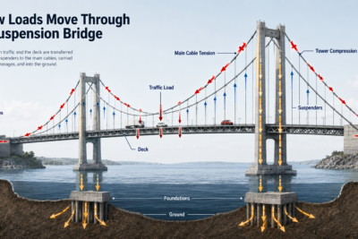
Suspension Bridge: Definition, History, and Examples
Beam Bridge: History, Mechanics, and Examples
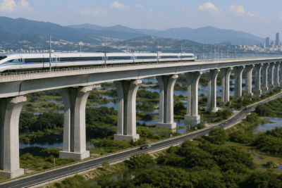
Viaducts: Definition, Uses, Types, Examples, and History
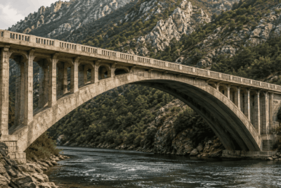
Arch Bridge: Definition, History, Types, Mechanics, and Examples
Pratt Truss Bridge: Design, Structural Mechanics, and Historical Significance
Related Entries: